FRCSR reads fcsr by copying it into integer register rd.
FSCSR swaps the value in fcsr by copying the original value into integer register rd, and then writing a new value obtained from integer register rs1 into fcsr.
FRRM instruction reads the Rounding Mode field frm and copies it into the least-significant three bits of integer register rd, with zero in all other bits.
FSRM swaps the value in frm by copying the original value into integer register rd, and then writing a new value obtained from the three least-significant bits of integer register rs1 into frm.
FRFLAGS and FSFLAGS are defined analogously for the Accrued Exception Flags field fflags.
Bits 31–8 of the fcsr are reserved for other standard extensions, including the “L” standard extension for decimal floating-point. If these extensions are not present, implementations shall ignore writes to these bits and supply a zero value when read. Standard software should preserve the contents of these bits.
Floating-point operations use either a static rounding mode encoded in the instruction, or a dynamic rounding mode held in frm.
Rounding modes are encoded as shown in Table. A value of 111 in the instruction’s rm field selects the dynamic rounding mode held in frm. If frm is set to an invalid value (101–111), any subsequent attempt to execute a floating-point operation with a dynamic rounding mode will raise an illegal instruction exception. Some instructions, including widening conversions, have the rm field but are nevertheless unaffected by the rounding mode; software should set their rm field to RNE (000).
The accrued exception flags indicate the exception conditions that have arisen on any floating-point arithmetic instruction since the field was last reset by software, as shown in Table 11.2. The base RISC-V ISA does not support generating a trap on the setting of a floating-point exception flag.
Instruction
000000000001_00000_001_01011_1110011
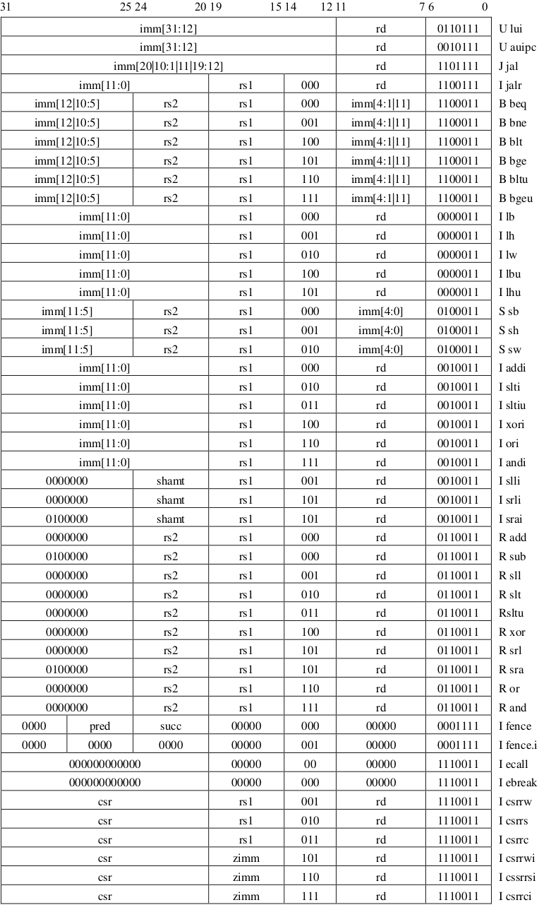
Load and Store Instructions
FLW : rd = M[rs1 + imm]
FSW : M[rs1 + imm] = rs2
Computational Instructions
FADD.S & FSUB.S & FMUL.S & FDIV.S & FSQRT.S
FMIN.S & FMAX.S
For the purposes of these instructions only, the value −0.0 is considered to be less than the value +0.0. If both inputs are NaNs, the result is the canonical NaN. If only one operand is a NaN, the result is the non-NaN operand. Signaling NaN inputs set the invalid operation exception flag, even when the result is not NaN.
FMADD.S : rd = (rs1 × rs2) + rs3
FMSUB.S : rd = (rs1 × rs2) - rs3
FNMSUB.S : rd = -(rs1 × rs2) + rs3
FNMADD.S : rd = -(rs1 × rs2) - rs3
The 2-bit floating-point format field fmt is encoded as shown in Table. It is set to S (00) for all instructions in the F extension.
All floating-point operations that perform rounding can select the rounding mode using the rm field with the encoding shown in Table.
Conversion & Move & SignInjection
FCVT.S.W : rd(float) = rs1(int)
FCVT.W.S : rd(int) = rs1(float)
FCVT.S.WU : rd(float) = rs1(uint)
FCVT.WU.S : rd(uint) = rs1(float)
FMV instructions are provided to move bit patterns between the floating-point and integer registers.
The bits are not modified in the transfer, and in particular, the payloads of non-canonical NaNs are preserved.
FCLASS.S instruction examines the value in floating-point register rs1 and writes to integer register rd a 10-bit mask that indicates the class of the floating-point number.
The top-level module of the FPU is fpnew_top and its interface is further described in this section. FPnew uses a synchronous interface using handshaking to transfer data into and out of the FPU.
All array types are packed due to poor support of unpacked arrays in some EDA tools. SystemVerilog interfaces are not used due to poor support in some EDA tools.
Parameters
The configuration parameters use data types defined in fpnew_pkg which are structs containing multi-dimensional arrays of custom enumeration types. For more in-depth explanations on how to configure the unit and the layout of the types used, please refer to the Configuration Section.
Parameter Name
Description
Features
Specifies the features of the FPU, such as the set of supported formats and operations.
Implementation
Allows to control how the above features are implemented, such as the number of pipeline stages and architecture of subunits
TagType
The SystemVerilog data type of the operation tag
TrueSIMDClass
If enabled, the result of a classify operation in vectorial mode will be RISC-V compliant if each output has at least 10 bits
EnableSIMDMask
Enable the RISC-V floating-point status flags masking of inactive vectorial lanes. When disabled, simd_mask_i is inactive
Ports
Many ports use custom types and enumerations from fpnew_pkg to improve code structure internally (see Data Types). As the width of some input/output signals is defined by the configuration, it is denoted W in the following table.
The following custom data types and enumerations used in ports of the FPU and are defined in fpnew_pkg. Default values from the package are listed.
roundmode_e - FP Rounding Mode
Enumeration of type logic [2:0] holding available rounding modes, encoded for use in RISC-V cores:
Enumerator
Value
Rounding Mode
RNE
3'b000
To nearest, tie to even (default)
RTZ
3'b001
Toward zero
RDN
3'b010
Toward negative infinity
RUP
3'b011
Toward positive infinity
RMM
3'b100
To nearest, tie away from zero
ROD
3'b101
To odd
DYN
3'b111
RISC-V Dynamic RM, invalid if passed to operations
operation_e - FP Operation
Enumeration of type logic [3:0] holding the FP operation. The operation modifier op_mod_i can change the operation carried out. Unless noted otherwise, the first operand op[0] is used for the operation.
FP to FP cast, formats given by src_fmt_i and dst_fmt_i
F2I
0
FP to signed integer cast, formats given by src_fmt_i and int_fmt_i
F2I
1
FP to unsigned integer cast, formats given by src_fmt_i and int_fmt_i
I2F
0
Signed integer to FP cast, formats given by int_fmt_i and dst_fmt_i
I2F
1
Unsigned integer to FP cast, formats given by int_fmt_i and dst_fmt_i
CPKAB
0
Cast-and-pack op[0] and op[1] to entries 0, 1 of vector op[2].
CPKAB
1
Cast-and-pack op[0] and op[1] to entries 2, 3 of vector op[2].
CPKCD
0
Cast-and-pack op[0] and op[1] to entries 4, 5 of vector op[2].
CPKCD
1
Cast-and-pack op[0] and op[1] to entries 6, 7 of vector op[2].
fp_format_e - FP Formats
Enumeration of type logic [2:0] holding the supported FP formats.
Enumerator
Format
Width
Exp. Bits
Man. Bits
FP32
IEEE binary32
32 bit
8
23
FP64
IEEE binary64
64 bit
11
52
FP16
IEEE binary16
16 bit
5
10
FP8
binary8
8 bit
5
2
FP16ALT
binary16alt
16 bit
8
7
The following global parameters associated with FP formats are set in fpnew_pkg:
1
2
localparam int unsigned NUM_FP_FORMATS = 5;
localparam int unsigned FP_FORMAT_BITS = $clog2(NUM_FP_FORMATS);
int_format_e - Integer Formats
Enumeration of type logic [1:0] holding the supported integer formats.
Enumerator
Width
INT8
8 bit
INT16
16 bit
INT32
32 bit
INT64
64 bit
The following global parameters associated with integer formats are set in fpnew_pkg:
1
2
localparam int unsigned NUM_INT_FORMATS = 4;
localparam int unsigned INT_FORMAT_BITS = $clog2(NUM_INT_FORMATS);
status_t - FP Status Flags
Packed struct containing the five FP status flags as logic in order MSB to LSB:
Memeber
Description
NV
Invalid operation
DZ
Division by zero
OF
Overflow
UF
Underflow
NX
Inexact operation
NaN-Boxing
RISC-V mandates so-called NaN-boxing of all FP values in formats that are narrower than the widest available format in the system. This means that all unused high-order bits of narrow formats must be set to '1, otherwise the value is considered invalid (a NaN).
Checks for whether input values are properly NaN-boxed are enabled by default but can be turned off (see Configuration). Narrow FP output values from the FPU are always NaN-boxed. Narrow integer output values from the FPU are sign-extended, even if unsigned.
FP32 is equal to RV32, so the operands are always boxed.
Handshake Interface
Both the input and output side of FPnew feature a valid/ready handshake interface which controls the flow of data into and out of the FPU. The handshaking protocol is similar to ones used in common protocols such as AXI:
An asserted valid singnals that data on the corresponding interface is valid and stable.
Once valid is asserted, it must not be disasserted until the handshake is complete.
An asserted ready signals that the interface is capable of processing data on the following rising clock edge.
Once valid and ready are asserted during a rising clock edge, the transaction is complete.
After a completed transaction, valid may remain asserted to provide new data for the next transfer.
The protocol direction is top-down. ready may depend on valid but validmust not depend on ready.
Operation Tags
Operation tags are metadata accompanying an operation and can be used to link results back to the oprerations that produced them. Tags traverse the FPU without being modified, but always stay in sync with the operation they were issued with.
Tags are an optional feature of FPnew and can be controlled by setting the TagType parameter as needed (usually a packed vector of logic, but can be any type). In order to disable the use of tags, set TagType to logic (the default value), and bind the tag_i port to a static value. Furthermore ensure that your synthesis tool removes static registers.
Mask for the status flags
This input is meant to be used in vectorial mode. The mask for the status flags is an input vector with NumLanes bits, and each bit can mask the status flags of a different FPU vectorial lane. This helps not make the final output flag signal dirty due to status flags from inactive lanes. If simd_mask_i[n] == 1'b0, the nth FPU lane will be masked for this operation and its resulting status flags will not be propagated to the final output status flag.
Configuration
Main configuration of the FPU is done through parameters on the fpnew_top module. A default selection of formats and features is defined in the package and can be controlled through these parameters. Furthermore, the project package fpnew_pkg can be modified to provide even more custom formats to the FPU.
Configuration Parameters
Features - Feature set of the FPU
The Features parameter is used to configure the available formats and special features of the FPU. It is of type fpu_features_t which is defined as:
Specifies the width of the FPU datapath and of the input and output data ports (operands_i/result_o). It must be larger or equal to the width of the widest enabled FP and integer format.
Default: 64
EnableVectors - Vectorial Hardware Generation
Controls the generation of packed-SIMD computation units in the FPU. If set to 1, vectorial execution units will be generated for all FP formats that are narrower than Width in order to fill up the datapath width. For example, given Width = 64, there will be four execution units for every operation on 16-bit FP formats.
Default: 1'b1
EnableNanBox - NaN-Boxing Check Control
Controls whether input value NaN-boxing is enforced (see NaN-Boxing). If set to 1, all values of FP formats that are narrower than Width will be considered NaN unless all unused high-order bits are set to '1. Output FP values are always NaN-boxed, regardless of this setting.
Default: 1'b1
FpFmtMask - Enabled FP Formats
The FpFmtMask parameter is of type fmt_logic_t which is an array holding one logic bit per FP format from fp_format_e, in ascending order.
1
typedef logic [0:NUM_FP_FORMATS-1] fmt_logic_t; // Logic indexed by FP format
If a bit in FpFmtMask is set, FPU hardware for the corresponding format is generated. Otherwise, synthesis tools can optimize away any logic associated with this format and operations on the format yield undefined results.
Default: '1 (all enabled)
IntFmtMask - Enabled Integer Formats
The IntFmtMask parameter is of type ifmt_logic_t which is an array holding one logic bit per integer format from int_format_e, in ascending order.
1
typedef logic [0:NUM_INT_FORMATS-1] ifmt_logic_t; // Logic indexed by integer format
If a bit in IntFmtMask is set, FPU hardware for the corresponding format is generated. Otherwise, synthesis tools can optimize away any logic associated with this format and operations on the format yield undefined results.
Default: '1 (all enabled)
Implementation - Implementation Options
The FPU is divided into four operation groups, ADDMUL, DIVSQRT, NONDOMP, and CONV (see Architecture: Top-Level). The Implementation parameter controls the implementation of these operation groups. It is of type fpu_implementation_t which is defined as:
The PipeRegsparameter is of type opgrp_fmt_unsigned_t which is an array of arrays, holding for each operation group for each format an unsigned value, in ascending order.
1
2
typedef logic [0:NUM_FP_FORMATS-1][31:0] fmt_unsigned_t; 		// Array of unsigned indexed by FP format
typedef fmt_unsigned_t [0:NUM_OPGROUPS-1] opgrp_fmt_unsigned_t; // Array of format-specfic unsigned indexed by operation group
This parameter sets a number of pipeline stages to be inserted into the computational units per operation group, per FP format. As such, latencies for different operations and different formats can be freely configured.
Default: '{default: 0} (no pipelining - all operations combinatorial)
UnitTypes - HW Unit Implementation
The UnitTypesparameter is of type opgrp_fmt_unit_types_t which is an array of arrays, holding for each operation group for each format an enumeration value, in ascending order.
1
2
typedef unit_type_t [0:NUM_FP_FORMATS-1]    fmt_unit_types_t;        // Array of unit types indexed by format
typedef fmt_unit_types_t [0:NUM_OPGROUPS-1] opgrp_fmt_unit_types_t;  // Array of format-specific unit types indexed by opgroup
The unit type unit_type_t is an enumeration of type logic [1:0] holding the following implementation options for a particular hardware unit:
Enumerator
Description
DISABLED
No hardware units will be generated for this format
PARALLEL
One hardware unit per format will be generated
MERGED
One combined multi-format hardware unit will be generated for all formats selecting MERGED
The UnitTypes parameter allows to control resources used for the FPU by either removing operation units for certain formats and operations, or merging multiple formats into one. Currently, the follwoing unit types are available for the FPU operation groups:
(all formats within operation group use same type)
PipeConfig - Pipeline Register Placement
The PipeConfig parameter is of type pipe_config_t and controls register placement in operational units. The requested number of registers is placed to predefined locations within the units according to the PipeConfig parameter. For best results, we strongly encourage the use of automatic retiming options in synthesis tools to optimize the pre-placed pipeline registers.
The configuration pipe_config_t is an enumeration of type logic [1:0] holding the following implementation options for the pipelines in operational units:
Enumerator
Description
BEFORE
All pipeline registers are inserted at the inputs of the operational unit
AFTER
All pipeline registers are inserted at the outputs of the operational unit
INSIDE
All registers are inserted at roughly the middle of the operational unit (if not possible, BEFORE)
DISTRIBUTED
Registers are evenly distributed to INSIDE, BEFORE, and AFTER (if no INSIDE, all BEFORE)
Adding Custom Formats
In order to add custom FP or integer formats to the FPU, it is necessary to make small changes to fpnew_pkg. New formats can easily be added by extending the default list of available formats, and/or by changing or removing the defaults.
Namely, the following parameters and types shall be adapted:
// For Int formats: localparam int unsigned NUM_INT_FORMATS typedef enum logic [INT_FORMAT_BITS-1:0] {...} int_format_e
Furthermore, the default configuration parameters shall be adjusted to match the dimensions of the modified format list.
No other changes should be necessary to the package or other source files of the FPU.
Architecture
The exact architecture of FPnew depends on the configuration through parameters. The main architectural traits as well as the effect of some parameters are described henceforth.
The design philosophy begind FPnew is that the “plumbing” of the architecture is quite regular and generic and the actual operations that handle the data are located at the lowest level. Handshaking is used to pass data through the hierarchy levels. As such, very fine-grained clock-gating can be applied to silence all parts of the architecture that are not actively contributing to useful work, significantly increasing energy efficiency.
Top-Level
The topmost level of hierarchy in FPnew is host to several operation group blocks as well as an output arbiter. The operation group is the highest level of grouping within FPnew and signifies a class of operations that can usually be executed on a single hardware unit - such as additions and multiplications usually being mapped to an FMA unit.
There are currently four operation groups in FPnew which are enumerated in opgroup_e as outlined in the following table:
Enumerator
Description
Associated Operations
ADDMUL
Addition and Multiplication
FMADD, FNMSUB, ADD, MUL
DIVSQRT
Division and Square Root
DIV, SQRT
NONCOMP
Non-Computational Operations like Comparisons
SGNJ, MINMAX, CMP, CLASS
CONV
Conversions
F2I, I2F, F2F, CPKAB, CPKCD
Most architectural decisions for FPnew are made at very fine granularity. The big exception to this is the generation of vectorial hardware which is decided at top level through the EnableVectors parameter.
Operation Group Blocks
Each operation group is implemented in its own operation group block, each generating slices. A unit type is selected for each format according to the settings in the Implementation parameter. Formats can either be implemented in a format-specific PARALLEL slice, or a multi-format MERGED slice. Both PARALLEL and MERGED slices can co-exist in case a subset of formats is assigned to both of the two options.
Format-Specific Slices (PARALLEL)
In a parallel slice, operational units capable of processing exactly one format are generated. If EnableVectors is set, operational units are duplicated into vectorial lanes in order to fill up the width of the datapath. Results from all lanes are collected and assembled at the output of the slice.
Implementing units as parallel slices usually yields best format-specific latency, however costs more in terms of area.
Multi-Format Slices (MERGED)
In a merged slice, operational units capable of processing multiple formats are generated. If EnableVectors is set, operational units for narrow formats are duplicated into vectorial lanes in order to fill up the width of the datapath. To facilitate vectorial conversions that update an input vector, the third operand is pipelined along with the operation in the CONV block. Results from all lanes are collected and assembled at the output of the slice.
Implementing units as merged slices usually yields best total area, however costs more in terms of per-format latency.
When the ADDMUL block is implemented using the MERGED implementation, multi-format FMA (multiplication done in src_format, accumulation in dst_format) is automatically supported among all formats using MERGED.
Pipelining
Pipeline registers are inserted into the operational units directly, according to the settings in the Implementation parameter. As such, each slice in the system can have a different latency. Merged slices are bound to thave the largest latency of the included formats.
All pipeline registers are inserted as shift registers at predefined locations in the FPU. For optimal mapping, retiming funcitonality of your synthesis tools should be used to balance the paths between registers.
Data traverses the pipeline stages within the operational units using the same handshaking mechanism that is also present at the top-level FPU interface. An individual pipeline stage is only stalled if its successor stage is stalled and cannot proceed in the following cycle. In general, different operations can overtake each other in the FPU if their latencies differ or significant backpressure exists in one of the paths. Hence, the use of operation tags is required to identify the exiting data if more than one operation is allowed to enter the FPU.
Output Arbitration
There are round-robin arbiters located at the ouputs of slices as well as the outputs of operation group blocks that resolve contentions for the ouput port of the FPU. Arbitration is fair, i.e. a unit cannot write the outputs twice in a row if other units are also contending for the output.